The Jodon CPS-2000 is designed to inspect serpentine convolution samples produced by a fin mill. Typically,a fin mill will produce an aluminum serpentine fin for use as a heat exchanger element in radiators, heaters, condensers, and evaporators. The cooling fin convolution trains exit the fin mill at a very high rate of speed,making an online measurement extremely difficult. As a consequence, the CPS-2000 is used as an off-line measuring system to precisely gauge dimensional characteristics against published cooling fin (air center) specifications.The CPS-2000 can be configured to gauge virtually any cooling fin.
The CPS-2000 incorporates two (2) extremely precise laser distance sensors to measure the profile of each convolution. One laser measures the rear-facing profile, and the other laser measures the forward-facing profile. Using a sophisticated differential process, the laser outputs are combined so as to provide a very precise measure of each convolution profile. After collecting the profile data, the system computes (1) convolution height, (2) height difference between successive convolutions, (3) contact radius of curvature of each convolution, (4) the convolution symmetry (i.e., “slant”), and (5) fin density (for example,convolutions per decimeter, or fins per inch).
To accommodate a wide variety of convoluted fin designs, and to allow multiple pass scanning, the laser sensors are mounted to precise X, Y, and Z axis translation stages. Those stepper-motor controlled stages permit the lasers to traverse the length of the sample (X-axis), and to make repeated (if desired) passes across the width of the sample (Y-axis). The Z-axis translator permits the lasers to approach the sample from the front (and back) while the X and Y axis scan is in progress. The Z axis, therefore, permits a very wide range of sample heights to be examined.
A variety of graphical presentations are available to the operator to permit a systematic analysis of fin mill performance. In addition to verifying the configuration of new tooling, the user can monitor for the start of potential problems such as air gaps (brazing failure), fin and tube height incompatibilities, and tool wear. Stored measurement data is also available for evaluating long-term fin mill performance, especially as it relates to anomalous trends.
HOW THE CPS-2000 OPERATES
To inspect cooling fin samples, the product of a fin mill is randomly selected and cut to a length representing at least one full rotation of the fin mill forming rolls. For instance, if the forming roll has 18 teeth, the prepared sample should have at least 18 measurable convolutions,and preferably more. Bear in mind that the more convolutions that the gauge is programmed to measure, the more time the test will take. The standard CPS-2000 fin holding fixture is capable of accommodating fin strips as long as 300 mm (12 inches). Depending upon the fin density of the strip,that sample length could amount to several revolutions of the forming rolls.
The prepared sample is then placed in an aluminum jig for properly securing the test piece for gauging. It is carefully laid into the fixture, leveled and secured so that it can be transferred to the CPS gauging system. The jig and fixture are made in such a way that virtually any convolution sample can be accommodated.
With the sample installed and clamped, the fixture is transferred to the gauge and inserted into the waiting fixture receiver.
The operator then determines how many convolutions to measure, and how many passes the gauge should make across the width of the sample. For a quick test, a single sweep across the center of the sample may suffice. For a more detailed examination, the operator may elect to scan at the sample center, and at each edge.

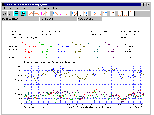
The CPS chart shown above displays individual heights and a statistical summary of a 50-convolution sample. Front and back results are shown for each of 3 regions across the width. Regions 1 and 3 represent the height near the top and bottom of each convolution. Region 2 measurements are from the midpoint of each convolution. (Note that region 2 is approximately 80 microns larger than regions 1 and 3.)
SPECIFICATIONS System Type: Non-contact electro-optical, multi-axis precision gauging system
Method of Measurement: Test piece placed in fixture and inserted into gauge. Laser distance measuring sensors (2) transported by orthogonally oriented linear stages (3) permit precise scanning of sample.
Fin Sample Material: Aluminum (or copper brass)serpentine convolution style cooling fins (air centers).
Light Source: Visible laser diode Wavelength: 670 nanometers Safety Code: CDRH Class II
Light Detection: Imaging on CCD array
Computer (Minimum): CPU: Pentium, 350MHz Ram: 64MB Hard Drive: 10GB Floppy Disk: 3.5 inch, 1.44MB Hard Disk: 10GBytes Backup: 100MBytes Zip Enhanced Keyboard (Industrial) Monitor: 15-inch, SVGA Mid Tower Enclosure
MEASUREMENT SYSTEM DESIGN CONSIDERATIONS
- Non-uniform convolution height from one convolution to the next
- Non-uniform convolution height across the span of each convolution
- Individual convolutions may have sideways curvature
- Sample materials may have high reflectivity
- Convolution profile measurements should be made on both sides of the test sample
- Louver panel test sample must be held in a way that does not distort the sample
- The user may require profile measurements of part or all of one or more convolutions.
SYSTEM CAPABILITIES
- Convolution height resolution of 0.0001 in.
- Convolution height accuracy of 0.0005 in.
- Measurement of convolutions per unit length
- Measurement of convolution contact radius
- Measurement of symmetry (“slant” or “lean”)
- Statistical summary of measurement results of each test
- PC-based operation, data storage, and graphing
- Long-term storage of results by roll or machine
- Tests customized to the user’s requirements for each louvertype or fin machine
APPLICATIONS
- Fin machine tool design
- Fin machine tool verification (user or supplier)
- Louver panel development and design
- Manufacturing process QC monitoring
- Continuing adjustment of louver height to correspond with tube crown height.
